  |
|
| FBE
AutoCAD Page |
|
| This tutorial has been prepared for students at the Faculty of
the Built Environment studying AutoCAD. It has been placed on the
Web to facilitate access by those students and because I believe
others may find the material of use! Note that throughout this document I am using the character " Stephen Peter, 17 July 2000 (7 October 1998). |
| Introduction |
|
| In this first tutorial you will learn how to start AutoCAD, save a drawing, and a range of common drawing commands. | |
| Starting AutoCAD |
|
|
Alternatively, click on the
AutoCAD icon |
Start AutoCAD by clicking on the Windows Start button (bottom left), then move the mouse to Programs then CAD and Modelling then "AutoCAD Architectural Desktop 2" and click on AutoCAD Architectural Desktop 2. A dialog giving various startup options will be displayed. Select the second option: "Start from Scratch" and click OK. |
| Despite
command line interfaces being considered totally archaic the command
area in AutoCAD is absolutely vital! One of the key things I'm trying
to "get you to do" in these tutorials is to watch the
command area! Using AutoCAD is like a conversation and AutoCAD's
half of the conversation comes from the text in the command area... |
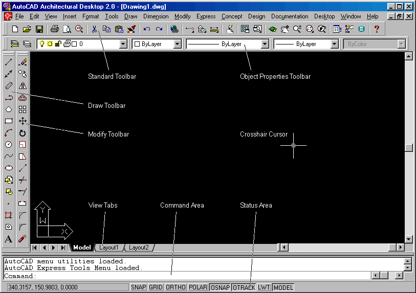
Once AutoCAD has loaded, move the mouse around until
you see a crosshair cursor. The AutoCAD window has a number of important
features:
|
| Command Entry |
||||||||||||||||||||
| Typically there are three ways of giving a command! | ||||||||||||||||||||
| Not all commands are on the Menus and/or toolbars! |
|
|||||||||||||||||||
| This means : type the text (qsave) and then press the Enter key (or the space-bar). | When I want you to type a command in the command area the AutoCAD command will be written like: | |||||||||||||||||||
type: QSAVE |
||||||||||||||||||||
| This means : click on the 'File' menu and then 'Save' (which should be one of the items on the 'File' menu). | When I want you to select a command from a menu, it will look like: | |||||||||||||||||||
| select File - Save | ||||||||||||||||||||
| AutoCAD also supports common shortcuts like Ctrl-S for Save!! | When I want you to pick a command from a toolbar, I'll write: | |||||||||||||||||||
| select Save | ||||||||||||||||||||
| Here I'm trying to cover all the bases by giving you the command to type, the menu options and showing you what the toolbar icon looks like! | Despite all of the above, I'll probably use a combination of the above like: | |||||||||||||||||||
select File - Save (or type
QSAVE |
||||||||||||||||||||
| Draw
a Rectangle |
||||||||||||||||||||
Select Rectangle (or type rectang |
||||||||||||||||||||
| The text typed is displayed in the command area at the bottom of AutoCAD's window. | 15,15415,315 |
|||||||||||||||||||
Hopefully AutoCAD drew a rectangle, which fits comfortably in
the AutoCAD graphics area!? If you can't see the rectanlge, type
z [space] a [space] (zoom all) - this instructs
AutoCAD to redraw the view, "zooming out" to show all
the graphics on the drawing. |
||||||||||||||||||||
| Saving a Drawing |
||||||||||||||||||||
Note that if you type SAVE The quickest way to save is to press Ctrl-S - this is the same as "qsave". |
Select the Save icon from the standard toolbar. The drawing has
not been saved before, so AutoCAD will display the SAVE AS dialog
box, select the appropriate Drive and Directory (for example: S:\arch\u1234567),
type the drawing name (for example TUT1), and
then select "OK". |
|||||||||||||||||||
| Draw some Lines |
||||||||||||||||||||
Instead
of LINE, you can also type:
LThe exact positions of these lines is not important. |
We will now draw some more graphics and then save and exit AutoCAD. | |||||||||||||||||||
Type LINE |
||||||||||||||||||||
| Move the crosshair to near the bottom-left of the rectangle and click the left mouse button, then move the crosshair to the top-right of the rectangle and again click the left mouse button. | ||||||||||||||||||||
| Remember this! If you press |
Press |
|||||||||||||||||||
| Draw a line from the top-left to the bottom-right of the rectangle,
and then press |
||||||||||||||||||||
| This will save the drawing and exit AutoCAD - don't PANIC! | Now type:QUIT |
|||||||||||||||||||
| You will be prompted to save the changes you've made - click OK. | ||||||||||||||||||||
| Starting
AutoCAD with an Existing Drawing |
||||||||||||||||||||
| To load a drawing, either click on the "Your Account" icon or start Windows Explorer and select the appropriate Drive and Directory. Once Explorer is showing the correct directory then double-click on your drawing. | ||||||||||||||||||||
| If you can't find your drawing (in Windows Explorer) then press F5 (function key 5), this tells Explorer to update the directory display; if you still can't find your drawing then perhaps you saved the drawing in some other directory - load AutoCAD and then select the File menu, at the bottom of the File menu is a list of recently opened drawings, select your drawing from the list. | ||||||||||||||||||||
| Coordinate Systems |
||||||||||||||||||||
| AutoCAD is a three dimensional CAD system, so you can enter XYZ values instead of the XY values shown here. | When specifying positions you can use Cartesian or Polar Coordinates.
Cartesian coordinates are simply a X value, a comma, and a Y value,
for example: 100,100.10<25. Angles are measured in degrees, with
|
|||||||||||||||||||
| Consider relative coordinates simply as distances! | The positions specified above are "absolute coordinates",
because they specify a particular position. AutoCAD can also use
"relative coordinates" to specify a position relative
to the current position, for example: @5.6,-3.4@16.32<62 |
|||||||||||||||||||
| Draw
a "Diamond" |
||||||||||||||||||||
| This
should draw a "diamond" (a rotated rectangle) shape. If you make a mistake, you can undo the last line segment by typing: u"c" means "close"
the shape. |
The "polyline" used below is used to create a sequence of joined line segments, which become one object. Using the "line" command each line segment is a separate object. | |||||||||||||||||||
Select Polyline (or type: pline
|
||||||||||||||||||||
| Snap Modes |
||||||||||||||||||||
| A simple way to turn Object Snap ON or OFF, is to click on "OSNAP" in the status Area. To see the various snap options "right-click" on "OSNAP" (in the status area) and select "Settings...". | It is often useful to be able to draw something from (for example) the end of another shape. AutoCAD has a large selection of "snap modes" for this purpose. The most commonly used snap modes are "Endpoint" (which snaps to the end of the selected graphics entity) and "Intersection" (which snaps to the intersection of two graphics entities). | |||||||||||||||||||
| To get AutoCAD to display the Object Snap Modes toolbar, select "Toolbars" from the "View" menu and then select "Object Snap". | The object snap modes can either be typed or they can be selected
from the standard toolbar |
|||||||||||||||||||
|
||||||||||||||||||||
| Draw an Arc |
||||||||||||||||||||
Select Arc (or type ARC
MID |
||||||||||||||||||||
 Figure 2 Arc construction. |
||||||||||||||||||||
| Finally... |
||||||||||||||||||||
Draw the rectangle
by selecting rectang |
Lastly, I want you to draw a rectangle in the diamond shape, another diamond inside that rectangle, a circle inside that diamond and a horizontal and vertical line also inside the last diamond (see figure 3)! Each shape should touch the Midpoints of the previous shape... | |||||||||||||||||||
Alternatively select the circle
icon 2p |
HINT: To draw the circle, select Draw - Circle - 2 Points and then (using midpoint snap) pick opposite sides of the inner diamond. | |||||||||||||||||||
| If you use the MIDpoint
Snap Mode for each point(!), you should be able to draw the shapes
without much trouble. If you make a mistake, press "Esc" (the "escape" key, located at the top-left of the keyboard). Then type
U |
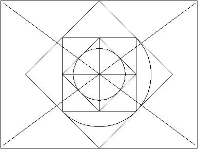 Figure 3 Finished Tutorial 1 drawing. |
|||||||||||||||||||
| Finishing up |
||||||||||||||||||||
| That's all for tutorial one! Save your drawing (press Ctrl-S)
and then exit AutoCAD (select File - Exit). Remember to log off before leaving. |
||||||||||||||||||||
| Tutorial 2 |
| Last Update : 17 July 2000 Major Revision : 17 July 2000 SEARCH . FBE SITEMAP |
Disclaimer
. Webmasters Page Contact : Stephen Peter Email : s.peter@unsw.edu.au |